Notes on Direct Current for Cambridge A level and UTME
Notes on Direct Current for Cambridge A level and UTME
Direct current : flow of charges in the circuit is in the same direction all the time from higher potential to lower potential.
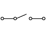
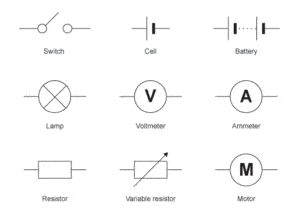
Appropriate circuit symbol
- switch
2. Cell, voltmeter, ammeter, resistor, variable resistor etc
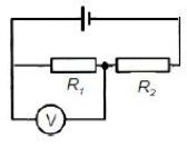
Circuit diagram
Kirchhoff’s First Law: The sum of the currents entering a junction is always equal to the sum of the currents leaving it(conservation of electric charge)
Kirchhoff’s Second Law: The sum of the electromotive forces in a closed circuit is equal to the sum of the potential differences (conservation of energy)
Derive, using Kirchhoff’s laws, a formula for the combined resistance of two or more resistors in series
Series arrangement
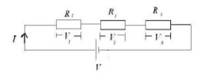
Resistors are said to be connected in series if current can flow from one resistor to another without branching.
V = V1 + V2 + V3
V1 = IR1
V2 = IR2
V3 = IR3
V = IR
IRt = IR1 + IR2 + IR3
Note
in series arrangement same current flows through the resistors but different voltage
Rt = R1 + R2 + R3
Parallel arrangement
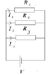
When resistors are connect in parallel current branches out but the voltage are the same for all the resistors
I = I1 + I2 + I3
I1 = V / R1
I2 = V / R2
I3 = V / R3
I = V / Rt
V / Rt = V/R1 + V/R2 + V/ R3
1 / Rt = 1 / R1 + 1 / R2 + 1 / R3
Example
Two cells of e.m.f. E1 and E2 and negligible internal resistance are connected into the network in the figure below
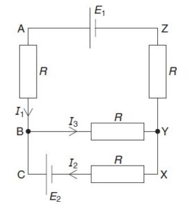
The currents in the network are as indicated in Fig. above
Use Kirchhoff’s laws to state the relation
(i) between currents I1, I2 and I3,
(ii) between E2, R, I2 and I3 in loop BCXYB,
(iii) between E1, E2, R, I1 and I2 in loop ABCXYZA.
Solution
According to Kirchhoff’s First Law: The sum of the currents entering a junction is always equal to the sum of the currents leaving it
Let junction B be our reference point
I1 is entering
I3 is leaving
I2 is entering
I3 = I1 + I2
(ii)
loop BCXYB
following anti-clockwise loop
conventionally current moves from positive terminal and “enters” negative terminal
But in E2 current leaves the negative terminal i.e E2 will be negative
I2 and I3 will also be negative because it opposes the direction of the loop
-E2 = -I2R – I3R
E2 = I2R +I3R
(iii)
loop ABCXYZA
following the anti-clockwise loop
Current leaves negative terminal of E2( this will give us -E2) and enters the negative terminal of E1( this will give us +E1)
I1 will be positive because it is in the direction of the loop
Resistors on A and Z are in series so current I1 flows without branching
I2 will be negative because it opposes the direction of the loop
E1 – E2 = I1R + I1R – I2R
E1 – E2 = 2I1R – I2R
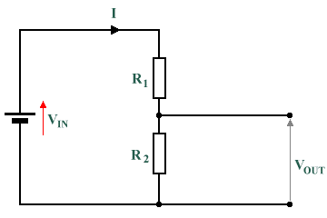
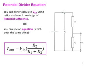
Show an understanding of the use of a potential divider circuit as a source of variable p.d.
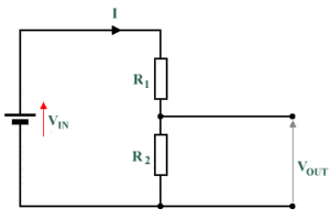
Vin = V1 + V2
V1 = IR1
V2 = IR2
Vin =IR1 + IR2
Vin = I(R1 +R2)
I = Vin / (R1 + R2)
V2 = Vin / (R1 + R2) * R2
V2 = Vout
Vout = R2 / (R1 + R2) * Vout
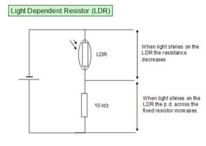
Use of thermistors and light-dependent resistors in potential dividers to provide a potential difference that is dependent on temperature and illumination respectively
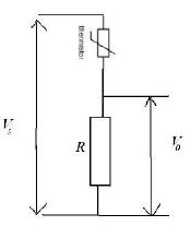
Thermistor as temperature sensor
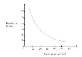
Temperature against the resistance of a thermistor
Recommended: Questions and answers on direct current for A level and UTME
